Can MIG Welding Be Used to Weld Aluminum?
Yes, MIG welding is widely used for aluminum fabrication. However, standard steel MIG setups will not work effectively. Aluminum welding with MIG demands a spool gun or push-pull feeder system to prevent the soft aluminum wire from bird-nesting in the drive rolls. Pure argon shielding gas is mandatory, as CO₂ blends cause oxidation and porosity. The power source must deliver constant voltage with sufficient amperage for the material thickness. When performing aluminum welding with MIG, the transfer mode must be spray transfer — short-circuit transfer does not produce adequate penetration or wetting for aluminum alloys. Inverter-based machines offer superior arc starts and inductance control, making them the preferred choice for professional aluminum welding with MIG.
Will the Weld Created by MIG Stick to the Aluminum Surface?
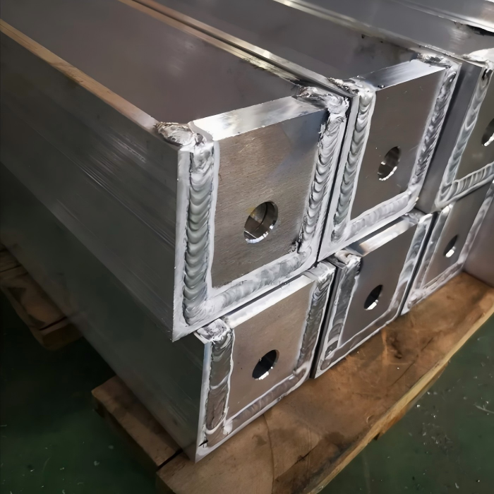
Proper aluminum welding with MIG produces a metallurgical bond, not just surface adhesion. The weld pool fuses with the base aluminum, creating a permanent joint—but only if the surface is free of oxides. Aluminum forms an oxide layer that melts at over 2,000°C, while the base metal melts at approximately 660°C. If this oxide is not removed mechanically or chemically, the weld bead will sit on top and may appear to adhere but will fail under stress.
For successful aluminum welding with MIG, use a stainless steel brush dedicated only to aluminum and remove the oxide immediately before welding. Acetone degreasing also improves wetting action. During welding, the puddle must visibly wet into the base material edges—this confirms actual fusion has occurred. Without this preparation, even skilled aluminum welding with MIG will result in weak, non-sticking joints.
What Are Common Mistakes When MIG Welding Aluminum?
Understanding common mistakes is essential for mastering aluminum welding with MIG. Incorrect wire feed speed and voltage balance tops the list—too much voltage burns through, while too little causes cold lap and stubbing. Using the wrong filler alloy is another frequent error; ER4043 and ER5356 are the most common, each suiting different base alloys and service conditions. Poor gun angle undermines the process because dragging pulls contaminants into the puddle, whereas pushing improves gas coverage. Travel speed errors are also prevalent—aluminum requires faster travel than steel, and slow travel overheats and causes sagging.
Inadequate cleaning guarantees porosity and lack of fusion. Worn contact tips are a hidden hazard, as aluminum wire expands when heated and a worn tip causes erratic arc and burnbacks. Ignoring preheat for thick sections—over 1/2 inch needs preheat to 150–200°C to avoid cracking. Neglecting interpass cleaning means each pass must be brushed before the next. Insufficient gas flow—set 20–30 CFH argon, as lower flow fails to shield the highly reactive molten aluminum. Avoiding these pitfalls transforms aluminum welding with MIG from frustrating to highly productive.
How Thin of Aluminum Can Be Welded Using MIG?
Thickness limitations are a critical consideration in aluminum welding with MIG. Standard constant-voltage MIG handles 0.063 inches (1.6 mm) reliably, while proper pulse technology can extend capability down to 0.040 inches (1.0 mm). For sheet metal under that threshold, TIG is often preferred over MIG due to burn-through risks. When welding thin sections, key techniques include using small-diameter wire (0.030 or 0.035 inches), keeping voltage low, and maintaining high travel speed to minimize heat input.
Additional measures further improve results on light-gauge material. Use a series of tack welds instead of continuous beads, and employ copper or aluminum backing bars to sink excess heat. Joint design also matters significantly—lap joints with tight fit-up allow lower heat settings and make aluminum welding with MIG more feasible on gauge materials. With these adjustments, even thin aluminum can be welded successfully while avoiding warping or burn-through.
Essential Equipment Setup for Aluminum Welding with MIG:
Power Source Selection:
Choose a MIG machine with at least 200 amps output for 1/4-inch aluminum. For production work, 300–400 amps improves duty cycle. Inverter-based power supplies give better arc starts and inductance control, which directly impacts the quality of aluminum welding with MIG.
Wire Feeding System:
Use a spool gun for occasional work. For high-volume jobs, install a push-pull feeder. The drive rolls must be U-groove type, not V-groove, because V-grooves deform soft aluminum wire. Teflon or polymer liners reduce friction. Keep the gun cable straight and short — under 15 feet if possible — to ensure consistent aluminum welding with MIG results.
Shielding Gas:
100% argon is standard for aluminum welding with MIG. For thick sections over 3/4 inch, argon-helium blends increase heat input. Helium improves penetration but costs more. Flow rate at 20–25 CFH for indoor shop work, increasing to 30 CFH outdoors or in drafty areas.
Filler Wire Selection:
ER4043 offers good crack resistance and wetting for aluminum welding with MIG. Use it for 6xxx series base alloys. ER5356 provides higher strength and better color match for 5xxx series marine alloys. Store wire in a clean, dry area — aluminum wire oxidizes quickly, so always use fresh wire from sealed containers.
Step-by-Step Welding Procedure for Aluminum Welding with MIG:
Step 1: Clean the base material. Remove all oil, grease, and dirt with acetone. Then brush with a new stainless steel wire brush in one direction only to avoid embedding oxides. This step determines whether your aluminum welding with MIG produces sound joints.
Step 2: Prepare joint edges. Bevel thick material to 60–70 degrees included angle. Leave a root face of 1/16 inch. For thin sheet, use a flanged butt joint or lap joint.
Step 3: Set machine parameters. For 1/8-inch aluminum, start at 22 volts and 450 inches per minute wire speed. Adjust based on arc sound and puddle fluidity. Spray transfer is essential — do not use short-circuit transfer for aluminum welding with MIG.
Step 4: Preheat if needed. Use a propane torch or electric heating pad. Monitor temperature with a contact pyrometer. Keep preheat below 250°F to avoid property degradation.
Step 5: Weld with push technique. Hold the gun at a 10–15° push angle. Maintain a stick-out of 3/4 inch for stable aluminum welding with MIG. Longer stick-out causes wire preheating and erratic feeding.
Step 6: Travel at steady speed. Watch the weld puddle trail — it should be oval and fluid. Increase speed if the puddle becomes too wide. Decrease speed if the toes do not wet out.
Step 7: Clean between passes. Wire brush each pass to remove surface oxide. This prevents entrapment and guarantees layer adhesion in multi-pass aluminum welding with MIG.
Step 8: Control crater fill. Aluminum craters crack easily. Use a crater fill function on the machine or pulse the trigger at the end to fill the depression.
Common Defects and Remedies in Aluminum Welding with MIG:
Porosity appears frequently in aluminum welding with MIG. Caused by moisture, oil, or oxide contamination, the solution is to clean thoroughly and increase shielding gas flow while checking for gas leaks in hoses and fittings.
Lack of fusion occurs with low heat or improper technique. Increase voltage and wire speed. Reduce travel speed. Ensure the arc is directed into the joint root.
Burn-through happens on thin material during aluminum welding with MIG. Lower voltage, increase travel speed, use pulsed MIG, or add a copper backup bar to absorb heat.
Cracking usually stems from improper filler selection or restraint. Use ER4043 for crack-sensitive alloys. Reduce joint restraint. Apply post-weld stress relief if possible.
Wire feeding problems like bird-nesting or burnbacks plague aluminum welding with MIG when drive roll tension is too high. Use light pressure, clean the liner, use a spool gun for long cables, and replace worn contact tips promptly.
Joint Design by Material Thickness:
For thinner aluminum sections—from 0.040 up to 0.063 inches—use a lap joint or flanged joint with no edge preparation and ensure a tight fit-up. For thickness from 0.063 up to 0.125 inches, a butt joint or T-joint works well with square edges and a gap no greater than 1/32 inch. For material from 0.125 up to 0.250 inches, prepare a single V-groove with a 60-degree included angle.
For thicker sections, more extensive preparation is required. From 0.250 up to 0.500 inches, use a double V-groove with a 70-degree included angle. For thickness over 0.500 inches, cut a U-groove with a 15-degree bevel and leave a 1/8-inch root face. Proper joint preparation reduces the heat input required, making aluminum welding with MIG more efficient and less distortion-prone across all thickness ranges.
Parameter Starting Points:
When using 0.045-inch wire for aluminum welding with MIG, set voltage at 21–23 volts and wire feed speed at 400–500 inches per minute for 1/8-inch material. For 1/4-inch material, increase to 23–25 volts and 500–600 inches per minute. For 3/8-inch material, use 25–27 volts and 600–700 inches per minute.
When using 1/16-inch wire, set 24–26 volts and 350–450 inches per minute for 1/4-inch material. For 3/8-inch material, increase to 26–28 volts and 450–550 inches per minute. For 1/2-inch material, use 28–30 volts and 550–650 inches per minute.
Adjust wire speed by listening to the arc during aluminum welding with MIG. A smooth humming sound indicates spray transfer. A crackling or popping sound means short-circuit transfer — increase voltage immediately.
Safety Precautions:
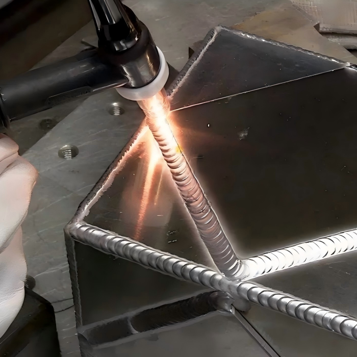
Aluminum welding with MIG produces intense UV radiation. Use a #10 or #11 shade lens. Wear fire-resistant clothing. Aluminum reflects light, so protect exposed skin. Fumes from aluminum welding with MIG include ozone and nitrogen dioxide — use local exhaust ventilation. Keep a Class D fire extinguisher nearby. Aluminum powder or chips from grinding are flammable, so clean the work area thoroughly after each session.
Quality Inspection Methods:
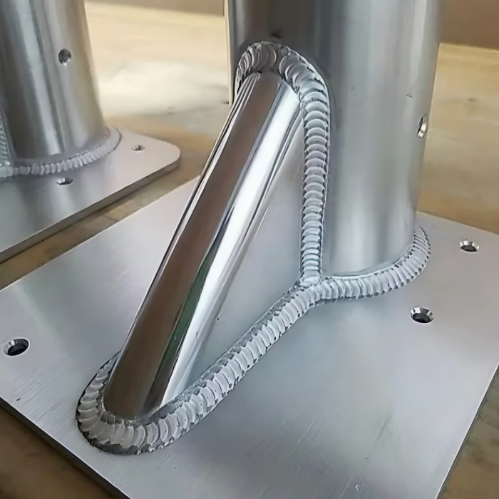
Visual inspection checks for uniform bead width and height, no surface porosity or cracks, complete toe wetting without undercut, and no discoloration from poor gas coverage. Destructive testing includes bend tests for ductility, tensile tests for strength, and macro etch for penetration depth. Radiographic or ultrasonic testing finds internal porosity. For critical structures, follow AWS D1.2 structural aluminum welding code to verify your aluminum welding with MIG meets standards.
Process Comparison:
MIG welding aluminum versus TIG welding: MIG is 3 to 5 times faster. MIG requires less operator skill. MIG produces less heat-affected zone distortion. TIG offers better control on thin materials and gives more aesthetic weld appearance. MIG costs lower per foot of weld. For production environments, aluminum welding with MIG is the clear productivity winner.
MIG welding aluminum versus laser welding: MIG handles thicker sections economically, while laser requires precise fit-up. MIG is portable and field-capable, whereas laser has higher capital cost. For most fabrication shops, aluminum welding with MIG offers the best balance of cost, speed, and versatility.
Applications Best Suited for MIG Aluminum:
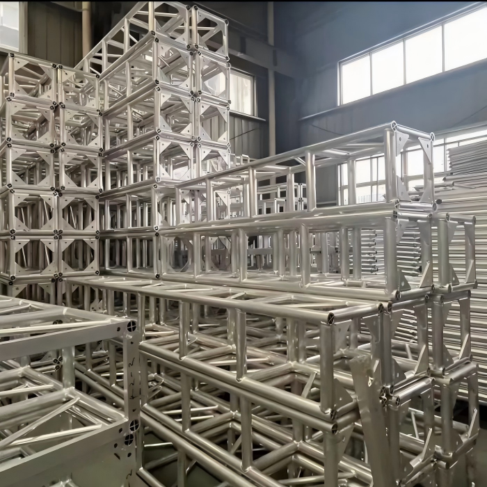
Aluminum welding with MIG excels in truck trailers and tankers, marine boat hulls and decks, architectural window frames, automotive body panels and engine components, pressure vessels and pipe spools, heat exchangers and refrigeration lines, and structural beams and columns. These applications benefit from the high deposition rates and consistent quality that aluminum welding with MIG provides.
Performance Optimization Tips:
Use a water-cooled torch for high-amperage work. Install a gas lens for better shielding coverage. Keep spare contact tips and liners on hand. Log settings for each material thickness and alloy. Train operators on sound recognition of proper arc. Perform daily wire feed system checks. Use pulse-on-pulse programming for vertical-up welding. Reduce inductance for thinner sections to flatten the bead. These refinements elevate aluminum welding with MIG from functional to exceptional.
Critical Requirements Summary:
The power source must be constant voltage with a minimum of 200 amps, and the wire feeder must be a spool gun or push-pull system with U-groove rolls. Shielding gas must be 100% argon at 20–30 CFH, while filler wire should be ER4043 or ER5356 with diameter matched to material thickness. Surface preparation requires degreasing plus stainless steel brushing immediately before welding. Gun angle must be 10–15 degrees push, and transfer mode must be spray transfer only.
Minimum thickness is 0.040 inches with pulse capability or 0.063 inches with standard equipment. Common mistakes include poor cleaning, wrong gas selection, slow travel speed, and worn contact tips. Weld adhesion is metallurgical fusion when properly prepared. Mastering these requirements ensures reliable aluminum welding with MIG in any shop environment.